|
|
|
|
Pix 18 |
Pix 23 |
Lesson 016 , Transceiver Construction - Audio Amp
This lesson covers the audio amp for the MP20, a simple bit of soldering that even Brian can do.
|
|
|
|
Pix 18 |
Pix 23 |
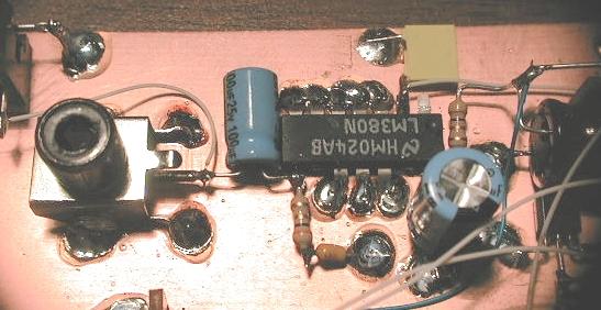
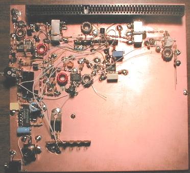
The largest component in this
circuit is C9, the 1000 uF electrolytic. Look at pix23. C9 is the large dark
object in the middle/left side. In pix18, you can see a bit of C9 on the far
right. You can use a bit of double stick take and secure the cap to the
board. Solder the negative lead of C9 to ground.
Prep the LM380 (U2) audio amp by bending pins 1,2 8 and 14 straight out. Bend
the remaining pins at a 45 degree angle from the body of the chip. Break off
pins 9 and 13. Clip the small parts of the pins from U2.
Solder U2 in place as seen in pix18. Connect R11, a three ohm limiting resistor
from pin#14 on U2 to the plus side of C9. Also solder C8 (220uF) to pin #14 and
ground.
Solder R17, another 3 ohm resistor to pin#8. Connect C19, 100nF from the free
end of R17 to ground. See pix18.
Connect the PLUS side of C41 (100uF) to pin#8. The other side of C41 is
the audio output. Solder to your favorite connector/jack. I connect my
audio out to both an RCA jack AND a mini stereo jack. Connect a volume
control from pin#2 to C7. You can use anything from 5k to 100k for the
volume control. I use a 10k pot. In the picture I show a temporary
trim pot (10k) for testing. Later I will use mini-coax shielded pairs to connect to a permanent volume control.
NOTE: in the picture you see a
component soldered from pin#2 to ground. This component is not on the schematic.
It is a 47nF cap used to roll off the high freq audio. You can experiment
using higher or lower value caps to suit your listening pleasure.
That's the end of the audio amp lesson. See Brian, I told you this one is easy
:-)
END OF LESSON #016