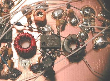
Looking at pix19, bend C21, the blue 470pF cap down at a 10 degree angle. Solder C27 and C24 as shown in the pix. Note the polarity of C27, the ORANGE varicap; has the FLAT side connencted to C21.
Lesson 017 , Transceiver Construction - IF (Intermediate Frequency) Amp
This lesson covers the IF amp for
the MP20. Another easy lesson dedicated to Phil...
Looking at pix19, bend C21, the blue 470pF cap down at a 10 degree angle. Solder
C27 and C24 as shown in the pix. Note the polarity of C27, the ORANGE varicap;
has the FLAT side connencted to C21.
Wind 30 turns of #28 gauge wire on a T37-2 (red) toroid. Make the windings nice and tight. Strip and tin the ends. Mount L3 using double sided sticky tape as shown in the pix19.
Prep U5, the MC1350 IF amp chip. Bend all leads straight out except pins 3 and 7. Bend 3 and 7 at 45 degree angles. Clip all the small portions of the pins on the chip. Position and solder the IF amp chip in place as shown in pix19 so that the end of C21 connects to pin#8
Solder pins 3 and 7 to ground. Solder C21 and one leg of L3 to pin#8. Solder the other end of L3 to pins #1 and #2. Also solder C28 and C29 from pins 1 & 2 to ground. Check the schematic and pix19.
Solder C32 (100nF) from pin#5 to
ground. Solder one end of R24 (5k1) to pin#5. Solder C33 from ground to
the free end of R24. Mount C33 in a vertical position, making it a
stand-off solder point for R25. This will be used when we build the AGC amp.
Build L5, a impedance matching transformer. Use the thicker black toroid. The
schematic shows 9:3 turns. I built my MP20 using 7:2 turns. Both will work fine.
One day when I get access to some nice test equipment, I'll tell you which is
better :-)
Strip and tin the wire ends. Mount L5 using double sided sticky tape. Solder the
7 or 9 turn winding wires to pins #4 and #6. Solder the upper 2 or 3 turn
winding to ground - see pix19. The other end of the 2/3 turn winding stays free.
This completes the IF amp.
END OF LESSON #017