Lesson 021 , Crystal Filter Circuit

This out-of-order lesson is dedicated to Andy, N8MX. For being way ahead of the class (as usual) The XTAL filter module is a nice break from the main xcvr board.

xcvr24.jpg (141388 bytes)  xcvr25.jpg (123000 bytes)
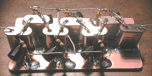
Depending if you have 5 xtals or 7 xtals, make a small copper board with dimensions 1 1/8 inches x 1 3/4 inches or 1 1/8 inches x 2 3/16 inches. Lightly clean the top of the xtals
with a Brillo pad or steel wool.  Pre-solder/tin the center of the copper board (3/8 inch strip down the middle). Pre-solder/tin the tops of the XTALS.  Solder the tops of the XTALS to the copper board as shown in the pix.


Bend the xtal leads as shown in the pix. PS: Brian, don't break them!

Form the leads of the 4 or 6 varactors as follows:
See pix24. Bend the ANODE lead 90 degrees. 1/4 inch down the lead, bend it 90 degrees again. Clip the last bend so that the lead is only 1/8 the inches long.

Solder all varactors to th copper board as shown on pix24.
Solder all XTALS together per pix25.
Solder one leg of a 100k resistor to the junctions of the varactors and xtals. Trim excess leads.

Solder a 100nF cap from ground to the free end of the 100k resistors.

NOTE. The schematic only shows one 100nF cap (C42).  It would be better
to wire it up with a 100nF bypass cap at the end of each 100k resistor.
Use the excess leads on the caps/resistors to interconnect all the
resistors - see pix24 and 25.

NOTE: the extra caps were not included with the mp20 kit (sri)

Run a short wire to connect both sides of the resistor/cap junctions.
See pictures.

Please note the updated xcvr schematic (version 1.5)

Hope the pictures make everything clear. One objective is to keep the wires from the xtals as short as possible to prevent capacitive effects between xtals.

THIS FILTER WILL BE VERY SHARP or WIDE depending on VARACTOR voltage.

END OF LESSON #021


Back to Lessons Page