Lesson 003 - Posted 03/02/01
FREQUENCY READOUT / COUNTER
! ! ! * * * C A U T I O N * * * ! ! !
BE CAREFUL WITH THE FC AND PLL CHIPS
IF YOU ARE NOT SURE HOW TO HANDLE STATIC SENSITIVE
PARTS, CALL DIZ ON THE PHONE @ 513.576.0066
FOLLOW EACH STEP BELOW USING YOUR SCHEMATICS.
Click on pictures to enlarge
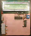
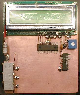
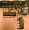
1. Position the LCD onto the board as shown.
Solder a bare wire from the copper board thru the holes
in the upper left, right and lower left corners of the LCD.
Also solder the wires coming from holes 1,5,7,8,9,and 10
to the copper board. These wires provide support and ground.
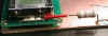
2. Remove a half inch piece of insulation from an 18 gauge
insulated wire. Place it over the lead coming from the "K"
side of the back-light display. Connect a 180 ohm 2 watt
resistor from the wire to the copper ground as shown.
If you don't have the resistor yet, wait until the next
shipment. This 180 ohm resistor will get very warm.
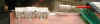
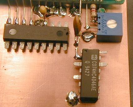
3. Position the 3 potentiometers on the board as shown. The values
could be anything from 10K to 100 K but there should be 3 identical pots in the kit along with one 1 K pot. On each pot, bend the right pin straight up. Bend the left pin down to the copper board and solder. The middle leads on the pots remain untouched. Solder a buss wire (18-24 gauge) to connect all the right side pins from the pots as shown in the picture. We just want to connect them together.
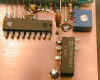
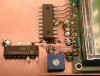
4. Find the PIC controller chip. Carefully bend all the leads from
the chip straight out, except pin # 5. Snip off the thin parts of the chip pins, as shown in the pictures. Place the PIC chip in-line with the LCD wires so that LCD holes 11,12,13 and 14 line up with PIC chip pins 6,7,8,9. The distance from the PIC chip to the LCD is about one half inch. Solder pin #5 on the PIC chip to the copper board. Connect the 4 wires from the LCD to pins 6,7,8 and 9 on the PIC chip. Clip and solder.
See above pictures
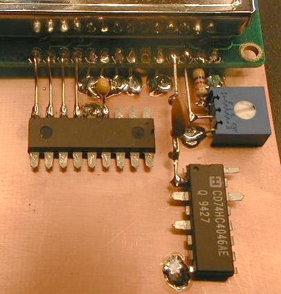
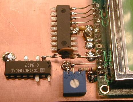
5. Connect a 100 nF cap from pin 4 on the PIC to ground and solder.
Take a 4k7 resistor and bend one lead at a right angle. Clip this lead to about 1/8 th inch and insert it thru the bottom of the LCD thru hole #2 and solder hole #2. Place the 1k pot as shown in the pictures and solder one leg to ground and another to the 4k7 resistor. Solder a jumper wire using a discarded resistor lead from LCD hole #3 to the center pin on the 1k pot.
See above pictures
6. Straighten the leads on the HC4046 chip and clip as before.
Carefully snip off pins 1,4,6,7,9,10,11,12,13 and 15. The only used pins are pins 2,3,5,8,14 and 16. Solder pin 8 onto the copper board as
shown.
7. Connect the 180 pF cap piggy-back onto the 430 ohm resistor, so
they are in parallel. Connect this component network between hole #4 on the LCD and pin #2 on the HC4046. Trim and SOLDER.
THIS COMPLETES LESSON-003
Back
to Lessons Page