Lesson 004
FREQUENCY READOUT / COUNTER
FOLLOW EACH STEP BELOW USING YOUR SCHEMATICS.
THE INTERCONNECTING WIRES IN THE PICTURE ARE
30 GA WIRE-WRAP STUFF AVAILABLE FROM RADIO
SHACK.
Telephone cross connect wire works well if you don't have 30ga cross connect wire.
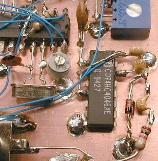
1. Using a clipped resistor lead, connect pins 3,5 and 16 on
the HC4046 chip; solder. Connect a 100 nF cap C3 from
pin 16 to ground on the same chip. Connect a 100 nF C2
cap on pin 14 and solder. Get 2 1N4148 diodes D1/D2 and
carefully twist them together back-to-back as shown in
the picture. Solder one end of the diodes to the last
100 nF cap C2, and the other end to ground. Connect another
100 nF cap C1 to the junction of the last cap C2 and the
diodes. Solder. Solder a 1K resistor R1 to the end of C1.
NOTE: In the schematic I switched the positions of C1 and R1.
Works the same either way. The other end of the 1K R1 resistor
will go to the freq source. Here you have some options.
A. Connect directly to the PLL output
B. Connect to a SPDT switch. This way you can use the counter
as a readout or a general purpose freq counter.
2.
Straighten the pins on the 10 MHz xtal as shown in the picture.
Cut the pins on the xtal to a length of one half inch.
Solder the xtal pins to the PIC chip, pins 15 and 16.
Carefully look at the small vari-cap, C6. Note that one of the
pins is connected to the center slot adjust. This is the grounded
side of the vari-cap. Looking at the picture, bend the top pin
on the vari-cap to the left at a right angle. Cut off about
1/8 th of an inch. Bend the other pin (the grounded pin) about
half way down the pin at a right angle. Solder the cap in place
as show in the picture. Last, connect a cap C5 from pin 15 on the
PIC chip to ground.
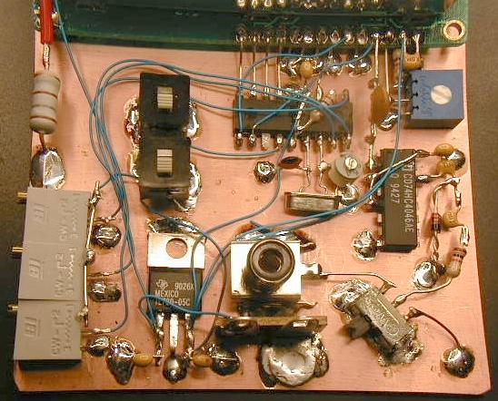
3.
This is a picture of the final "working" freq counter. You will see
some optional switches and connectors. The 1k resistor, R1 is connected
to the center pole on a SPDT switch. One end of the switch will go to
the PLL output. The other end goes to an RCA jack for general purpose
freq counter operation.
4.
Power for the FC comes from the included 5 volt regulator. Clean the
tab end on the regulator with steel wool or scrape the tap end with a
screwdriver to expose clean metal. Solder the tab end to the copper
board as shown in the picture. Solder the center lead to the copper.
The other 2 pins should come straight out and float above the copper.
Connect a 100 nF cap from the left leg of the regulator to ground.
repeat for the right leg of the regulator.
5. Connect
three wires from the output of the regulator to pin 16 of the
HC4046 chip, pin 4/14 of the PIC chip and pin 2 on the LCD. The easiest
way to do this is to take 3 each 3.5 inch wires and connect all three
together at one end by stripping and twisting the wires together. Solder
this end to the right leg of the regulator. Trim each one of the wires
and connect to the three destinations. Connect a wire from the left
side of the regulator to the "A" pin hole on the LCD. This is the other
side of the LED backlight on the LCD, marked with a "+" on the top side
of the LCD.
6. The 2
switches in the upper left are S1 (offset +/-) and S2 (offset Y/N).
Wire these as shown in the schematic. If you are not using these switches,
then ground pin 13 on the PIC chip and connect the 3 pots with the common
connection to the 5 volt power source.
7. Connect the center pins on pots R3, R4 and R6 to pins 1, 17 and 18
on the PIC chip. Add the remaining connections from the LCD to the
PIC chip. Follow the schematic carefully. This completes the
construction of the MP20 frequency display/counter.
Next is calibration.
THIS COMPLETES LESSON-004