FOLLOW EACH STEP BELOW USING YOUR SCHEMATICS.
IN THIS LESSON, WE'LL POWER UP AND
CALIBRATE THE FREQ COUNTER.
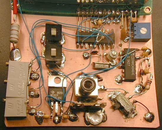
1. Connect the input of the FC to ground. You can use a short
jumper clip lead or solder the loose end of R1 to ground.
Adjust the contrast control R5, the 1k pot to center position.
Apply 12 volt power to the regulator IC. +12 goes to the
left leg in the picture. The display should show something.
Check to make sure that nothing is getting hot, except maybe
the 180 ohm 2 watt resistor used to limit the current to the
backligh LED. If you have a display and nothing is getting hot,
adjust the 3 pots, R6, R4 and R3 until you get a "0" reading.
All pots will be either fully clockwise or counterclockwise.
2. Obtain a calibrated frequency source. It should be greater than
1 MHz and less than 30 MHz. If you don't have an accurate source,
use the output of a known QRP transmitter.