Lesson 007 - PLL Construction

PLL Construction - Second of two lessons

1.  Get a copper board that is 6 x 6 inches or larger.
    Make sure the edges of the board a smooth.
    Clean the copper surface with a soft abrasive.

  pll1.jpg (18962 bytes)
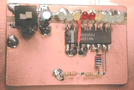
2.  Position C25, the 1000pF vari-cap as shown in pix-1.  If you
    do not have a large cap, just leave a 2 inch wide space for it.
    I used some double stick tape to mount the cap.  Then I soldered
    5 large gauge (14-18 ga) stranded wires from the metal on the cap
    to the copper board.

pll2.jpg (22820 bytes)   pll3.jpg (20046 bytes)

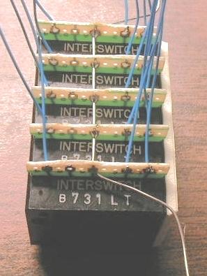
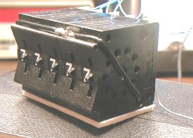
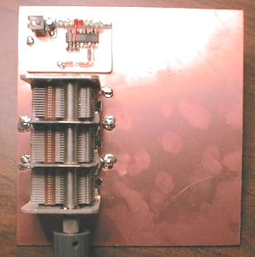
3.  Wire up your 3 octal switches.  Use 3 inch 30 ga wires and solder
    them into the holes labeled 1, 2 and 4.  No not solder anything
    into the hole labeled 8.  Do not strip the other end of the 30 ga
    wires yet. Place a solid 6 inch wire thru the holes labeled "A"
    and let the ends float freely.  See pix-2.  Solder the solid wire
    on each switch.

    Place some double stick tape on the bottom of the switches. See pix.
    Run a wire thru the hole as seen in the pix and wrap it around the
    switches as seen in the pix and solder the ends together.  This will
    help keep the switches together.

    If we get more switches after this Spring, I'll ship them out.
    your switch set should look like pix-2 and pix-3.

pll4.jpg (23561 bytes)
4.  When you get your 20 meter band module kit, you'll find the parts
    to build the VCO voltmeter as described in lesson #6.  Position the
    voltmeter circuit behind the cap as in pic-1.  We'll hook up the
    VCO display later after the PLL is tested.

NEXT: Ref Osc and PLL chip hookup! Study the PLL chip!!!

Back to Lessons Page