THE MOST DIFFICULT CIRCUIT IN THE MP20.
YOU GET THIS BUILT & THE REST IS DOWNHILL....
This lesson may look hard, but it's just 1 part soldered at a time - no big deal - just go slow.
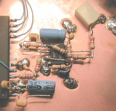
See the above picture and the schematic as reference for parts layout.
Solder a 2k7 (R4) to pin #4 on the PLL. Solder a 22n (C6) from the other end of the 2k7 to ground. The 22n cap should be labeled "223". Solder another 2k7 (R5) to the junction of R4 and C6.
Prepare the LMC662 IC (U2) by straightening all pins EXCEPT pin #4. CAUTION, the LMC662 is a CMOS device and need careful anti-static handling. Position the LMC662 IC so that R5 can be soldered to PIN #2 of U2 as in the picture (do not solder yet). Solder the ground pin #4 on U2 to the copper board.
Build a network of components with C13 (10n), C14 (47n) and R11 (27k); look at the picture and the schematic. Solder the network of three components to pins #1 and #2 on U2.
Solder a bare wire jumper between pins #3 and #5 on U2.
Solder the free end of the 2k7 (R5) to pin #2 on U2.
Solder R7 (10k) and C12 (3u3) from pin #5 to ground. Make sure you observe the polarity on C12; the (+) side goes to Pin #5.
Solder C10 (100n) and C11 (33u) from pin #8 to ground. Again, observe the polarity on the 33uF cap; the (+) side goes to pin #8.
Form a 10k resistor (R6) and solder it from pin #6 to #7 as in the picture.
Form a 10k resistor (R8) and solder it from pin #6 to #1. This resistor should just lay on top of the U2 IC.